Due to request, here is a tutorial on how to create two different kinds of rig UI sliders in Blender 2.5.
 |
3D View Slider
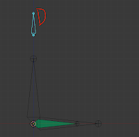
1. Select the rig and hit tab to go into edit mode. Hit shift-S and hit cursor to center. Hit shift-A to add a bone. Hit G and then Y to move it up on the y axis as shown to the right. Name the bone D and tab back to pose mode
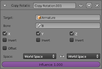
2. Select C and go to it's bone constraints, right click on the last constraint's influence slider and add a driver. The slider will turn purple to show it has a driver.
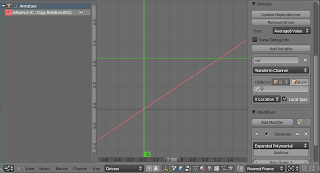
3. Open a graph editor panel. Hit the "N" key to bring up the properties panel. In that panel under the drivers tab we're going to change some settings. First change the driver type from scripted expression to averaged value. Under transform channel, in Ob/Bone, type armature and another text box will pop up. In that box type D. Also put a check in the local space box. We will leave x location as is since we want to use the x location to drive the rotation influence.

Note: If the properties panel goes blank, click the influence driver in the upper left hand corner of the graph editor. It will turn white when selected.
If you move bone D around you'll see its already driving C's rotation constraint. When D is at 0, the constraint is off and when D is at 1 on the x-axis the constraint is on. What if we wanted it to turn on at 0.5.
4. Go back to the graph editor and scroll down to the modifiers tab of the properties panel. Hit the x to the right of generator to delete the modifier. Now the red line in the timeline is gone.
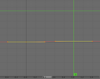
5. In the timeline right click at frames 0 and 1. This will add keyframes we will use to specify the drivers length.
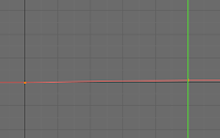
6. Select both keyframes in the timeline by hitting the A key with the mouse over the timeline view. Hit shift-T and select linear and the keyframes won't have handles anymore.
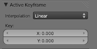
7. Right click the keyframe at frame 0 to select it. In the Active Keyframe tab in the properties panel make sure the x and y values are both 0.000.
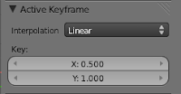
8. Now select the keyframe at frame 1 and change the x value to 0.5 and the y value to 1.0 as shown to the right.
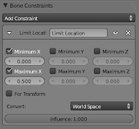
9. Select bone D and add a limit location constraint. Check Minimum X and Maximum X and change Maximum X to 0.5.

10. With bone D still selected, go to the 3D view and hit the N key for the properties panel(if its not there already). Scroll to the top and lock the y and z locations and your done.
Before we move on to the next step, save this file and call it "3Dslider". Then save it again as "Nslider" to create a new file instead of saving over the old one.
N panel Slider
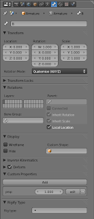
1. With bone B selected go to bone properties. Scroll down to custom properties, open that tab and add a property.
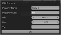
2. In that property click the edit button. In the window that opens up input the settings as shown to the right and hit ok. If you look in the properties panel of the 3D view you should see a slider under a new "properties" tab labeled "Copy B"(if you have bone B selected). You will probably have to open the properties tab to see it.
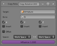
3. As we did before, with bone C selected, go to bone constraints and in the last copy rotation constraint's influence slider add a driver.
4. Go to the graph editor and select the driver we made by clicking on the influence text in the upper left hand corner.
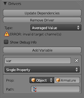
5. In the properties panel of the graph editor we're going to change some settings in the drivers tab. Change scripted expression to averaged value and transform channel to single property. Next to object, type armature. A new path panel will pop up, we'll put something here in a minute.

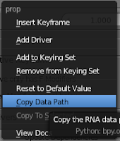 6. Go to your 3D view and select bone B. Go to the slider we made.
 Right click the slider and hit copy data path.
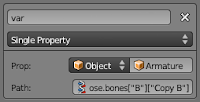
7. Go back to the graph editor to that path panel we left blank. Mouse over it and hit ctrl-V to paste the data path we copied. Now the slider should work. If it does your done.
So now you've hopefully learned how to create two different kinds of sliders. I say hopefully because this is my first tutorial. If your confused that means I probably skipped something so if you have any questions leave a comment below.

Hi michael sorry if i've posted this twice, i followed your tutorial above and understand it basicly. only snag i hit was Number 5. nothing happens when i right click, no keys to edit are made. 2nd part followed and it worked ok. is there any chance you can tell me how to drive shape keys on a mesh using this system? I will do some trial and errors to discover but a point in the right direction would be great. greetings from Ireland, Paul
ReplyDelete